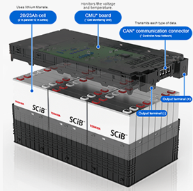
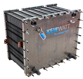
HYBRIS project aims at developing a hybrid energy-storage system (HESS) to connect to the alternate-current (ac) grid. The HESS features two battery technologies: Lithium Titanium Oxide (LTO) and Aqueous Organic Redox Flow (AORF) batteries. LTO technology is characterized for high power capabilities; that is, it can provide fast response when high power demand is required. However, LTO suffers from reduced energy storage capabilities. On the other hand, AORF features high energy capacity, reduced cost, and simple maintenance, but its energy storage efficiency greatly diminishes at high power operation.
The union of both battery technologies into a hybrid system allows achieving arbitrary values of energy capacity and power rating by simply combining different proportions of both battery technologies, thus providing flexibility on the sizing of the storage system. This allows a reduced size and cost, compared to the same system but employing only one of the battery technologies. Moreover, it allows the AORF battery to work at maximum efficiency, making profitable the investment made in the hybrid system and making it more sustainable.
A key piece to enable the hybridization of the system is the power conversion system (PCS). Both LTO and AORF batteries provide the energy at direct current (dc), but the energy must be delivered or sourced from the grid in the form of ac. The power converters allow converting the electrical energy from dc to ac and vice versa, enabling the energy transfer from the batteries to the grid, from the grid to the batteries, and even between batteries. The internal configuration of the PCS can be conceived employing different type and number of converters, distributing the power among multiple converters operating in parallel, and with a wide variety of components to select from to conceive the converters.
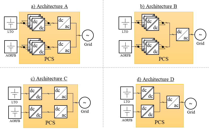
The converters principle of operation consists of employing magnetic elements and capacitors (passive devices) to momentarily store the energy from the input and then deliver it to the output at the required current mode and voltage. To connect/disconnect these elements to/from the converter ports, power semiconductor devices (active devices) are employed, e.g., transistors and diodes. This cycle is repeated tens of thousands of times per second, such the energy storage capacity of the passive devices can be greatly reduced, allowing highly compact converters. In this framework, HYBRIS partners IREC and CEA have studied multiple configurations with the aim of performing a multiobjective optimization. The considered configurations, also known as conversion architectures, are shown in Figure 2. Both batteries require a dc-dc converter previous to the dc-ac converter in order to increase the voltage to a suitable value, around 800 V. Then the dc-ac converter can properly transfer energy to and from the ac grid. The batteries are coupled at the ac grid (architectures A and C) or after the dc-dc converters (architectures B and D). We also consider up to three dc-dc converters operating in parallel to distribute the conversion losses and reduce the components temperature (architectures A and B).
The optimization study has the following objectives:
- Minimization of the PCS energy losses (Ploss). An ideal power converter would have zero energy losses, such that the same amount of power sourced from the input is delivered to the output; i.e. a 100% conversion efficiency. However, due to multiple physical processes, part of the processed energy is lost, usually reaching efficiency values between 90% to 99%. We compute the losses on the converters through comprehensive electrothermal models of the different components and the data available from the components datasheets.
- Minimization of the PCS capital cost (Ccapital). The components composing the power converters have a material and manufacturing cost that must be considered. The sum of both concepts defines the PCS capital cost. We have obtained the cost for each component type (semiconductors, capacitors, copper conductors, etc.) from literature and component providers for order quantities in the range of tens of thousands of units, thus accounting for scale economies. The cost value is then modeled as a function of constructive parameters of the components, i.e., the semiconductor area, copper conductor weight, heatsink volume, etc.
- Minimization of the cost derived from PCS reliability (Creliability). The reliability of the PCS, that is, the probability of it not failing at a given time, is dependent on the harshness of its operation. For instance, the higher the operating temperature of the components, the most probable they will fail, and the lower its reliability. Also, the higher the number of converters, the most probable one of them may fail. A failure of a given component in a converter usually leads to the shutdown of the converter and in some case of the whole PCS. We translate the reliability to cost by considering the reparation cost and the revenue loss due to the system partial- or complete-shutdown time. We compute the reliability of the system through the mathematical Markov chains method and component’s reliability data available from the literature.
We define the optimization problem with the following objective function:
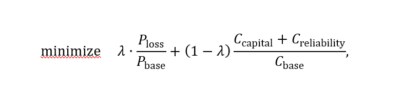
where variables Ploss, Ccapital ,and Creliability are a function the following parameters:
- The commercial components used in each converter.
- The configuration of the magnetic components in each converter.
- The operation parameters of the converters.
- The size of the heatsinks attached to the semiconductor devices.
Moreover, the optimization problem is subject to various constraints, the most relevant being:
- The components cannot surpass a given maximum temperature.
- The semiconductor devices must fit the available mounting area of the heatsinks
- In the magnetic elements, the copper windings must fit inside the magnetic core available winding space.
- The magnetic field through the magnetic cores cannot surpass the value specified by the manufacturer.
- The gird currents distortion at the nominal operating power cannot be higher than 10%.
Parameters Pbase and Cbase allow normalizing the losses and costs such that both objectives are comparable. Their values are set to 1000 W and 1000 €, respectively. Parameter λ allows either prioritizing the minimization of the losses or the cost. For instance, λ=1 minimizes only the losses, while λ=0 does similar but to cost.
We use an optimization solver from MATLAB® to solve the problem, executing it for each architecture and for three values of λ parameter, prioritizing cost (λ=0.2), losses (λ=0.8) and giving equal priority to both (λ=0.5). The solver outputs many viable solutions of the PCS configuration that comply with the stablished constraints. Figure 4 shows the cloud of solutions for the four architectures. In the figure, the closer a given solution is to the axes origin, the lower the objective function is, and thus the better the result is. The solutions in the frontier of the point clouds in Figure 4 define the so-called Pareto front (dashed lines in Figure 4). A given solution is part of the Pareto front if there are no alternative solutions that improve one of the objectives, e.g., cost, without worsening the other objectives. This way, the Pareto front allows identifying the existing trade-offs of the system. In the present case, in the four architectures, the PCS features a clear tradeoff between losses and cost. For example, we can increase the cross section of the copper conductors in the magnetic elements to reduce the losses, but this will come on the expense of an increased cost. In the extremes of the Pareto front, a small improvement on one of the objectives comes with a large aggravation of the complementary objective. Thus, there is a minimum achievable value of the PCS cost and losses. Figure 4 also reveals that the PCS architectures with a lower number of converters achieve overall lower losses and cost.
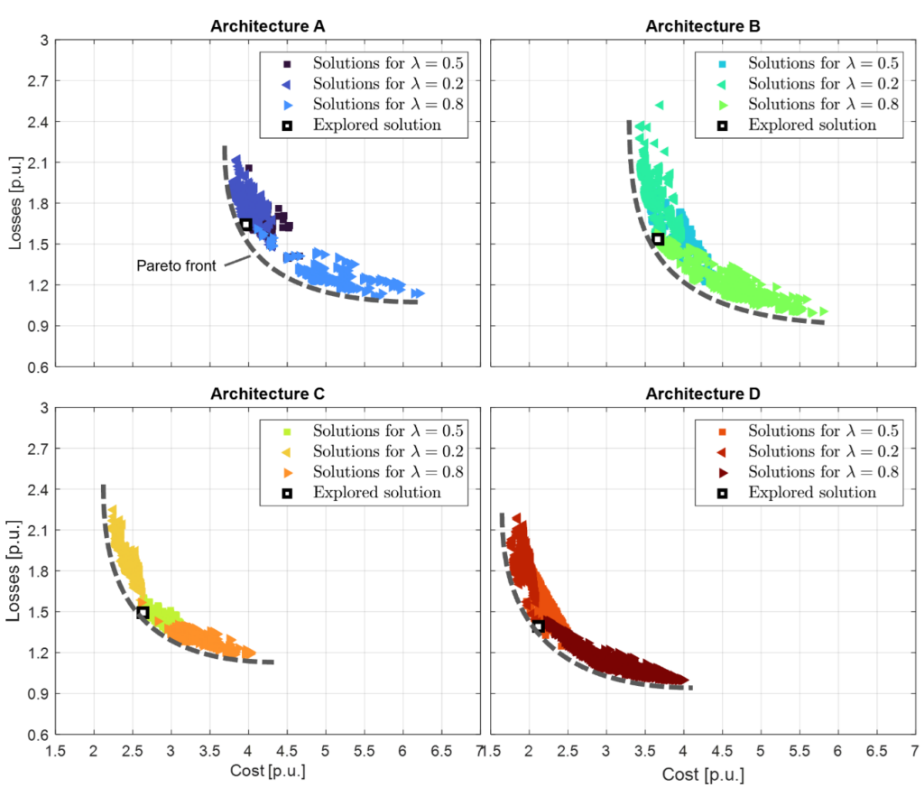
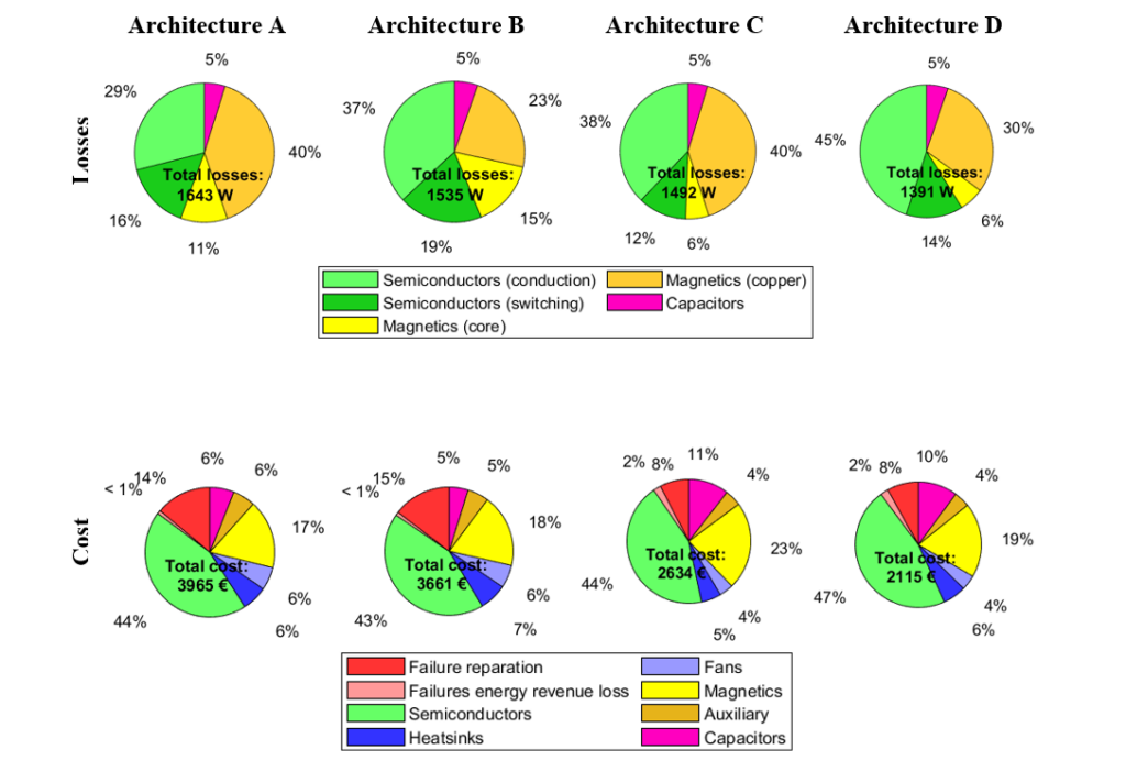
For each architecture, let us explore in detail a representative solution, marked with a black and white square in Figure 3. Figure 5 breaks down the losses and cost among the relevant components and concepts of the PCS for each selected solution. From Figure 5 we can see that the PCSs featuring a dc-ac converter for each battery (architectures A and C) feature proportionally higher magnetic losses and lower semiconductor losses than architectures with a single dc-ac converter (architectures B and D). Reducing the number of parallel dc-dc converters leads to a reduction of the magnetic losses while semiconductor losses are barely affected. Considering the nominal power of the PCS (59 kW), the conversion efficiencies are 97.2%, 97.4%, 97.5%, and 97.6% in architectures A, B, C, and D, respectively.
Figure 5 shows that on all cases, semiconductors account for almost 50 % of the system cost. The second largest capital cost are magnetic elements, followed closely by the reparation cost, the cooling system cost (heatsinks plus fans), and the capacitors cost. The cost of the auxiliary components and the cost penalty from revenue losses are marginal in all cases (≤ 6%). Overall, Architectures C and D feature lower material costs. Although there is some linear dependency of each component cost with its power rating, thermal resistance, etc., still a fixed cost is present in the form of package cost, manufacturing cost, auxiliary components, etc. Thus, the higher the number of components in an architecture, the higher the system cost.
In conclusion, for the present HESS, the PCS architecture featuring a single dc-dc converter per battery and a single dc-ac converter (architecture D) stands as the optimum solution, featuring the best trade-off between cost and efficiency. It is worth noting that if we consider higher revenue loss penalties from failure-induced system shutdown, the architectures with a higher degree of parallelization may become cost competitive. Moreover, the optimum architecture may be different if the system power rating is substantially lower or higher. In the upcoming months, partners IREC and CEA will work together to build a low power demonstrator to validate the optimal HESS PCS.
Written by Àlber Filbà, Oriol Esquius, Lluís Trilla, Clàudia Cabré i José Luís Domínguez, from IREC.